
User manual for the Exar XRP6141 evaluation board, covering description, pinout, power‑up, schematics, BOM and layout.
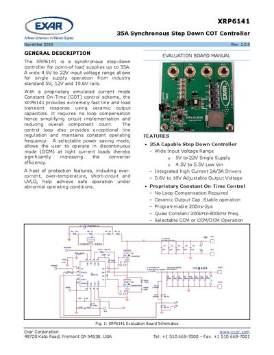
The Exar XRP6141 evaluation board manual provides a complete overview of the synchronous step‑down controller, its features, and how to set up the board. It includes a general description, pin assignments, power‑up procedure, schematics, bill of materials and board layout.
The document also details jumper settings for Forced CCM or DCM/CCM operation, protection features, and revision history, helping engineers quickly evaluate and prototype designs using the XRP6141 controller.
| Maximum Output Current | 25 A |
|---|---|
| Input Voltage Range | 4.5 V – 22 V |
| Adjustable Output Voltage | 0.6 V – 18 V |
| Switching Frequency | 200 kHz – 800 kHz |
| Current Capability | 35 A |
| Power‑saving Mode | Discontinuous mode (DCM) selectable |
The rated output current is 25 A.
Set jumper J1 to the CCM position; the converter will operate in Forced CCM at VIN = 12 V.
The controller provides over‑current, over‑temperature, short‑circuit and UVLO protection.
Pulling EN/MODE above 1.9 V turns the IC on in Forced CCM; raising it above 3.0 V selects DCM or CCM depending on load.