
Emtronix ETR232i evaluation board manual covering hardware interfaces, connector pin definitions, jumpers, and mechanical dimensions.
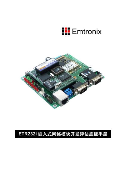
This manual describes the ETR232i embedded network module development evaluation board from Emtronix. It lists the board's 14 hardware connectors and two jumpers, their locations, and usage. It also applies to the ETR232H module because the development evaluation boards are identical.
The document provides signal definitions for connectors such as CN1 power input, CN2 Ethernet, CN3 COM1 debug port, CN4 COM3 RS232, CN5 COM3 RS485, CN6 and CN7 expansion buses, CN8 COM2, and CN9 LCD, plus jumper settings and an appendix with mechanical dimensions. This manual is written in Chinese.
| Module core | R1610C |
|---|---|
| Module dimensions | 74 mm x 53 mm |
| Power input | +5 V DC |
| Ethernet interface | 10M/100M compatible RJ45 |
| COM1 | 3-wire RS232, RS232 level, debug port |
| COM3 (RS232) | 3-wire RS232, RS232 level |
| COM3 (RS485) | RS485 bus interface; COM3 selectable RS232/RS485 |
| COM2 | 9-wire RS232, TTL/CMOS level |
| Expansion bus CN6 | 20-pin IDC, simplified ISA bus |
| Expansion bus CN7 | 10-pin IDC, high address lines |
| LCD interface CN9 | 20-pin IDC |
| GPIO interface CN10 | 16-pin IDC, can connect matrix keyboard |
| SIM card socket CN11 | SIM card socket for GPRS |
| MC39i connection CN12 | ZIF 40-pin socket on board back |
| Module connection | 36-pin IDC socket x2 |
| JP1 | 2-pin SIP selects debug or run mode |
| JP2 | 3-pin SIP selects COM3 RS232 or RS485 |
| Default RS485 drive mode | TX-driven mode |
| CS1 default address range | 300h-37Fh |
| CS0 default address range | 200h-27Fh; can be set to memory mode |
CN1 accepts +5 V DC.
Short JP1 for debug mode; leave it open for normal run mode.
Short JP2 pins 1-2 for RS232 or pins 2-3 for RS485.
No; the provided RS485 is not optically isolated, but it can be modified.