
The Autonics TX4S Series PID Temperature Controller User Manual provides installation, wiring, parameter settings, alarm functions, and safety guidelines.
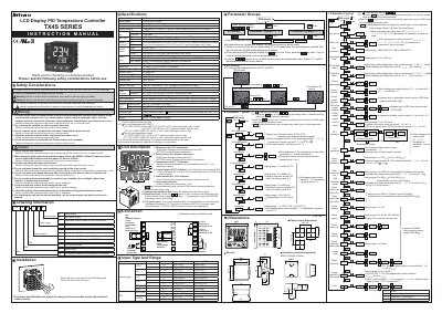
This manual explains how to install and safely operate the Autonics TX4S Series PID Temperature Controller. It includes safety considerations, mounting instructions, wiring recommendations, and guidelines for avoiding hazards such as electric shock and fire.
The document details the controller’s specifications, input sensor options, control and alarm output types, RS485 Modbus communication settings, and parameter configuration procedures such as auto‑tuning, hysteresis, and alarm options. Troubleshooting tips and a Modbus mapping table are also provided.
| Power supply voltage | 100-240VAC 50/60Hz |
|---|---|
| Allowable voltage range | 90 to 110% of rated voltage |
| Power consumption | Max. 8VA |
| Display method | 11 segments (PV: white, SV: green), LCD |
| SSR output rating | 12VDC ±2V 20mA |
| RS485 communication protocol | Modbus RTU |
| RS485 baud rates | 2400‑38400 bps |
| Ambient temperature range | -10 °C to 50 °C |
| Protection IP rating | IP50 |
| Dielectric strength | 3 kVAC for 1 min |
The controller requires a power supply of 100‑240VAC at 50/60 Hz, and the allowable voltage range is 90 % to 110 % of the rated voltage.
Use the PC loader port with an EXT‑US converter cable (sold separately) and a SCM‑US USB‑to‑Serial converter (sold separately) to communicate with DAQMaster software on the PC.
The controller provides Alarm output 1 (AL1) and, on models that support it, Alarm output 2 (AL2), both rated at 250VAC 3A 1a.