
Analog Devices ADP151 Evaluation Board User Guide

UG-116 explains how to set up and use the Analog Devices ADP151 evaluation board for basic regulator measurements.
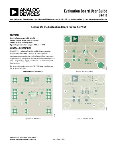

Analog Devices ADP151 Evaluation Board User Guide - cover page
Brand
Analog Devices
Category
Other Electronics
Document type
User Manual
Language
English
Pages
12
File format
PDF
File size
298 KB
Published
10 November, 2026
Updated
10 November, 2026
Model
ADP151
MD5 checksum
1D220628BBE355653310B1E319180F25

About this manual

This guide covers the ADP151 evaluation board hardware, configurations, and measurement setups for output voltage, line and load regulation, dropout voltage, and ground current.

It also includes connection steps for TSOT, WLCSP, and LFCSP board versions and a bill of materials.

What's inside

  • Features
  • General Description
  • Evaluation Boards
  • Evaluation Board Hardware
  • Evaluation Board Configurations
  • Measuring Output Voltage
  • Line Regulation Measurements
  • Load Regulation Measurements
  • Dropout Voltage Measurements
  • Measuring Ground Current

Specifications

Input voltage range2.2 V to 5.5 V
Output current range0 mA to 200 mA
Output voltage accuracy±1%
Operating temperature range-40°C to +125°C

Frequently asked questions

What is the input voltage range of the ADP151?

The input voltage range is 2.2 V to 5.5 V.

What is the output current range?

The output current range is 0 mA to 200 mA.

When does ground current drop below 1 µA?

Ground current drops to less than 1 µA when the device is disabled (EN = GND).

Which components are common to all evaluation board versions?

C1, C2, and J1 are common to all versions.

Download PDF (298 KB)

More Analog Devices Manuals


View all Analog Devices manuals →