
The Dell PowerConnect W-IAP100 Series Wireless Access Points deliver high-performance IEEE 802.11n WLANs. The access point provides 802.11n functionality at both 2.4 GHz and 5 GHz, as well as concurrent support for legacy 802.11 a/b/g wireless services, utilizing MIMO (Multiple In, Multiple Out) and other high-performance transmission techniques.
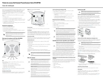
This Portuguese-language installation guide covers the Dell PowerConnect W-IAP100 Series wireless access points, specifically the W-IAP104 and W-IAP105. It describes the hardware: the four status LEDs (PWR, ENET, 11A/N and 11B/G/N), the external antenna connectors of the W-IAP104 versus the internal antennas of the W-IAP105, the console port, the auto-sensing 10/100/1000Base-T RJ-45 Ethernet port with IEEE 802.3af PoE support, the DC power input and the Reset button used to return the access point to factory settings.
The guide also lists the package contents, a pre-installation checklist, and the five-step setup process. It explains how to choose installation locations and avoid RF absorbers, reflectors and interference sources, how to mount the unit on an indoor wall using the keyhole slots or on a standard 15/16" ceiling rail, and how to connect the Ethernet cable. Safety and regulatory notes on FCC and EU statements, RF exposure and authorized configuration are included at the end. This manual is written in Portuguese.
| Wireless standard | IEEE 802.11n at 2.4 GHz and 5 GHz, with simultaneous support for 802.11a/b/g |
|---|---|
| Ethernet port | One MDI/MDX 10/100/1000Base-T (RJ-45) auto-sensing port |
| Power over Ethernet | IEEE 802.3af compatible, 48 V DC powered device (PD) |
| Antennas | W-IAP104: four external antenna connectors; W-IAP105: internal antennas |
| Cable | Category 5 UTP cable up to 100 m long, 4 or 8 conductors |
| Status LEDs | Four: PWR, ENET, 11A/N, 11B/G/N |
| Wall mount screw spacing | 4.7 cm between the two screws |
| Ceiling rail size | Standard 15/16" ceiling mounting rail |
| RF exposure distance | Minimum 35 cm between the radiator and your body |
Power off the access point, press the Reset button with a small narrow object such as a paper clip, then power it on while still holding the button. The power LED blinks after 5 seconds and again 15 seconds after you release it, indicating the restart is complete and the unit starts with factory default settings.
The W-IAP104 is designed for use with external antennas and has four external antenna connectors, while the W-IAP105 has internal antennas.
It can be powered through IEEE 802.3af Power over Ethernet from a PSE such as a midspan injector or a PoE-capable network infrastructure; when PoE is not available, a separately sold Dell power adapter kit can be used.
A Category 5 UTP cable with 4 or 8 conductors, up to 100 m long, is used for the auto-sensing 10/100/1000Base-T RJ-45 port.