
This document introduces the features and usage of Parker Hannifin PV series electro-hydraulic proportional controls for axial piston pumps.
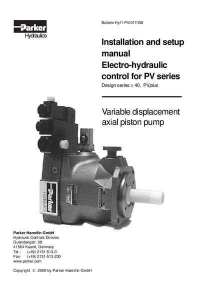
The manual provides step‑by‑step instructions for installing and configuring the electro‑hydraulic proportional controls used with Parker PV series axial piston pumps. It covers the three control variants – basic proportional displacement, pressure‑compensated, and closed‑loop pressure control – and details the required hydraulic and electrical connections.
Key sections include wiring diagrams, power‑supply requirements, gain and ramp adjustments, basic compensator setup, and diagnostic values. Tables list size‑specific settings, maximum horsepower, and LVDT signal ranges to aid proper commissioning and troubleshooting.
| Power supply voltage | 22 - 36 VDC |
|---|---|
| Module current requirement (basic version) | ≈ 1.4 A |
| Input command options | 0‑10 V voltage or 0‑20 mA current |
| Nominal solenoid current for full displacement | 1.3 A |
| Maximum horsepower for PV080 | 78 kW |
The module requires a power supply of 22 V to 36 V DC.
Displacement can be commanded with either a 0‑10 V voltage signal or a 0‑20 mA current signal.
The nominal current for the solenoid at full displacement is approximately 1.3 A.