
The 6 mm temperature transmitter is developed based on the microprocessor technology, with small size, fast response, excellent quality and low total cost of ownership to provide superior performance and anti-electromagnetic interference for dedicated applications. It can be installed horizontally or vertically, without any gaps between devices.
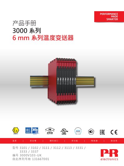
This installation guide from PR electronics A/S covers the 3000 series 6 mm temperature transmitters in models 3101, 3102, 3111, 3112, 3113, 3331, 3333 and 3337 (document 3000V103-UK, Chinese edition 3000V103-CN). It opens with warnings, symbol meanings and safety notes, then describes UL installation and cFMus installation in Division 2 or Zone 2, and IECEx/ATEX installation in Zone 2.
The guide explains the flexible power supply options for the transmitters, including direct or loop wiring with 24 VDC ±30%, supply via the power rail with the 9410 power control unit or the 3405 power module, and the related protection fuses. It then covers mounting on and removal from DIN rail or power rail, supply of the power rail, marking labels and side labels, applications, technical characteristics, ordering, accessories, technical specifications, connections, front LED indicators and DIP switch configuration including default configuration and temperature range setting. This manual is written in Chinese.
| UL file number | E314307 |
|---|---|
| Wire size | AWG 26-12 / 0.13 x 2.5 mm2 stranded |
| Screw terminal torque | 0.5 Nm |
| Protection fuse, DIN rail / rail solution | 2.5 A |
| Current supported by power rail supply terminals | max. 400 mA |
| IECEx approval | Ex nA IIC T4 Gc (IECEx KEM 10.0068 X) |
| ATEX approval | II 3G Ex nA IIC T4 Gc (KEMA 10ATEX0147 X) |
| cFMus approval | Class I, Div. 2, Groups A, B, C, D T4 / Class I, Zone 2, AEx nA IIC T4 |
| Power output of 9410 power control unit | up to 96 W |
| Minimum enclosure protection, Zone 2 installation | IP54 |
They can be supplied directly or by loop wiring with a 24 VDC ±30% supply, protected by a 2.5 A fuse.
The 3111, 3112 and 3113 models have power rail connectors; 24 VDC can be connected to any one of them to supply the other devices on the rail.
Wire size AWG 26-12 (0.13 x 2.5 mm2 stranded) with a screw terminal torque of 0.5 Nm.
The document states a 5-year product warranty period.