
This manual describes how to use Anritsu's handheld spectrum analyzers, including the Handheld Spectrum Master™, Site Master™, Cell Master™, and BTS Master™.
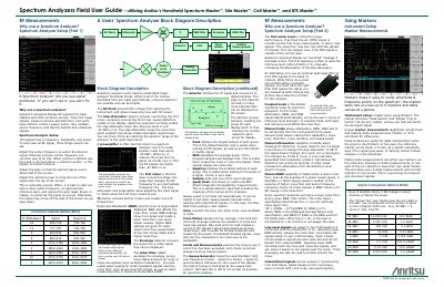
This field user guide explains how to use Anritsu handheld spectrum analyzers, including the Spectrum Master, Site Master, Cell Master and BTS Master. It describes the spectrum analyzer block diagram and the purpose of the DC block, step attenuator, preamplifier, first mixer, IF section, RBW and VBW filters, detector, trace modes, limits and sweep generator.
The guide covers spectrum analyzer setup, including center frequency, span and reference level settings, and explains why a spectrum analyzer is used to see signal problems, measure carriers and distortion, and verify base stations. It also covers markers, detector types, manual and coupled mode operation, common cellular bands and dBm-to-watts conversion.
| Preamplifier noise floor reduction | about 10-15 dB |
|---|---|
| Step attenuator effect | raises the noise floor when enabled; allows measuring higher signal levels |
| Preamplifier use | weak signals lower than about -50 dBm |
| Preamplifier turn-off | RF signals higher than -40 dBm or so |
| Displayed markers | up to 6 markers and delta values |
| Marker delta reference | six delta measurements using marker 1 as reference |
| RBW noise floor change | 10 dB change for every 10 times change in RBW |
Set the span so that the desired signal covers about half of the screen.
It helps prevent overdriving the first mixer; excessive level at the first mixer causes distortion visible on the display.
Use it for weak signals lower than about -50 dBm, and turn it off if RF signals are higher than -40 dBm or so.
Peak is the default detector, displaying the largest sample of each group.