
This manual introduces the assembly method of digital logic board, including parts list and assembly steps
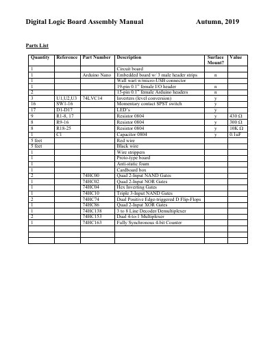
This document serves as an assembly manual for a Digital Logic Board kit compatible with the Arduino Nano. It provides a detailed parts list including the embedded board, power supply, headers, switches, LEDs, resistors, capacitors, and a variety of logic gate chips such as 74LVC14, 74HC00, and 74HC138. The kit also includes necessary tools like wire strippers and anti-static foam.
| Embedded Board | Arduino Nano |
|---|---|
| Power Connector | Wall wart w/micro-USB connector |
| Inverters | 74LVC14 |
| NAND Gates | 74HC00 Quad 2-Input NAND Gates |
| NOR Gates | 74HC02 Quad 2-Input NOR Gates |
| Flip-Flops | 74HC74 Dual Positive Edge-triggered D Flip-Flops |
| Resistor Value | 0804 |
| Capacitor Value | 0.1uF |
Develop a logic expression for the circuit to be implemented.
Ensure the pins are aligned with the holes before attempting to insert the part.
Discharge static electricity accumulated on your body before touching the boards or logic packages to prevent chip destruction.