
This document is the product manual of STSR30 synchronous rectifier smart driver. The driver adopts SO-8 package, the working voltage range is 4V-5.5V, the typical peak output current is 1.5A, the operating frequency is 20 to 500KHz, and it can automatically turn off the output with a duty cycle less than 14%. It can also operate in discontinuous mode.
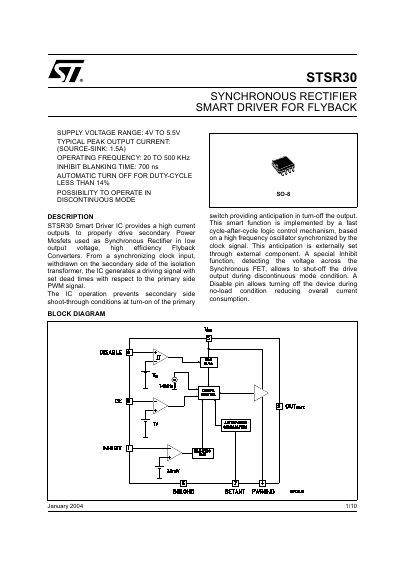
The STSR30 is a Smart Driver IC designed to drive secondary power MOSFETs used as synchronous rectifiers in low output voltage, high efficiency flyback converters. It generates driving signals synchronized with a clock input from the secondary side of the isolation transformer, featuring set dead times relative to the primary side PWM signal to prevent shoot-through conditions.
The device includes a fast cycle-after-cycle logic control mechanism for anticipation in turn-off, an inhibit function to shut off the drive output during discontinuous mode, and a disable pin to reduce current consumption during no-load conditions. It operates with a supply voltage range of 4V to 5.5V and supports typical peak output currents of 1.5A.
| Supply Voltage Range | 4V to 5.5V |
|---|---|
| Typical Peak Output Current | 1.5A |
| Operating Frequency | 20 to 500 KHz |
| Inhibit Blanking Time | 700 ns |
| Storage Temperature Range | -40 to +150 °C |
| Operating Junction Temperature Range | -40 to +125 °C |
| Thermal Resistance Junction-case | 40 °C/W |
| Thermal Resistance Junction-ambient | 160 °C/W |
The supply voltage range is from 4V to 5.5V.
The typical peak output current is 1.5A for both source and sink.
The inhibit blanking time is 700 ns.
The operating frequency range is from 20 to 500 KHz.