
The UC3572 is a negative output flyback pulse width modulator which converts a positive input voltage to a regulated negative output voltage. The chip is optimized for use in a single inductor negative flyback switching converter employing an external PMOS switch. The block diagram consists of a precision reference, an error amplifier configured for voltage mode operation, an oscillator, a PWM comparator with latching logic, and a 0.5A peak gate driver. The UC3572 includes an undervoltage lockout circuit to insure sufficient input supply voltage is present before any switching activity can occur, and a pulse-by-pulse current limit. Output current can be sensed and limited to a user determined maximum value. The UVLO circuit turns the chip off when the input voltage is below the UVLO threshold. In addition, a sleep comparator interfaces to the UVLO circuit to turn the chip off. This reduces the supply current to only 50µA, making the UC3572 ideal for battery powered applications.
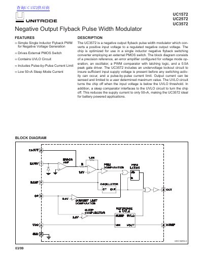
The UNITRODE UC1572, UC2572, and UC3572 are negative output flyback pulse width modulators designed to convert a positive input voltage to a regulated negative output voltage. These devices are optimized for use in single inductor negative flyback switching converters employing an external PMOS switch. The chip includes a precision reference, an error amplifier, an oscillator, a PWM comparator with latching logic, and a 0.5A peak gate driver.
| Reference Voltage (3VREF) | 3.06 V |
|---|---|
| Oscillator Frequency | 115 kHz |
| Error Amp Gain | 90 dB |
| Gate Drive Output High Saturation | 0.7 Vv |
| Supply Current (Sleep Mode) | 150 hA |
| Maximum Duty Cycle | 96 % |
| Undervoltage Lockout Start Threshold | 4.5 Vv |
| Operating Frequency Range | 10kHz to 200kHz |
The recommended operating frequency range is 10kHz to 200kHz.
The maximum supply current in sleep mode is 150 hA when VCC is 30V and CS is 3V.
The maximum duty cycle is 96% when EAINV is +100mV and VCC is between 5V and 30V.