
PM6686 is a dual step-down controller with adjustable output voltages, adjustable LDO and charge pump circuit for notebook power systems. This application note describes the PM6686 demonstration kit, which represents a typical application circuit, and allows testing of all the functions of the PM6686 device. The demonstration kit provides two switching sections with 5 V (OUT1) and 3.3 V (OUT2) outputs from 8 V to 28 V input battery voltage. The operating switching frequency of the two sections is 400 kHz and 300 kHz, respectively. Each switching section delivers more than 5 A of output current. An internal linear regulator can provide 5 V at 100 mA peak current. The charge pump circuit provides an auxiliary 12 V output voltage.
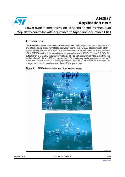
The document provides an overview of a demonstration kit based on the PM6686 dual step-down controller. This device is designed for notebook power systems, featuring two switching sections with adjustable output voltages (5V and 3.3V) from an input range of 8V to 28V. The kit allows users to test all functions of the chip, including charge pump circuits and internal linear regulators.
| Input voltage range | 5.5 V to 28 V |
|---|---|
| OUT1 output voltage (adjustable) | 0.7 V to 5.5 V |
| OUT2 output voltage range | 0 V to 2.5 V |
| Switching frequency OUT1 | 400 kHz |
| Switching frequency OUT2 | 300 kHz |
| Output current capability | >5 A per section |
The device supports an input voltage range from 5.5 V to 28 V.
The kit supports dual fixed outputs of 1.05 V/3.3 V or 1.5 V/5.0 V.
The operating switching frequency for the first section is 400 kHz.