
STMicroelectronics AN2938 PM6686 Power System Demo Kit Application Note

AN2938 Application note introduces the demonstration kit based on the PM6686 dual step-down controller with adjustable output voltages and adjustable LDO for notebook power systems.
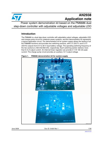

STMicroelectronics AN2938 PM6686 Power System Demo Kit Application Note - cover page
Brand
STMicroelectronics
Category
Power Management
Document type
Application Note
Language
English
Pages
39
File format
PDF
File size
1.8 MB
Published
06 August, 2012
Updated
30 September, 2023
Model
PM6686
MD5 checksum
4640D9FAE1FCE4279E7515D8C0D15F31

About this manual

The document provides an overview of a demonstration kit based on the PM6686 dual step-down controller. This kit allows users to test all functions of the chip, including two switching sections with adjustable outputs (5V and 3.3V) from an input range of 8V to 28V, as well as an internal linear regulator and charge pump circuit.

What's inside

  • Main features
  • Demonstration kit schematic
  • Jumper settings
  • Component list
  • Test setup and performance summary
  • Representative waveforms
  • Operating modes
  • Fault management

Specifications

Input voltage range5.5 V to 28 V
OUT1 output current> 8 A
Switching frequency400 kHz / 300 kHz
LDO output current100 mA peak

Frequently asked questions

What is the input voltage range for the PM6686 demonstration kit?

The kit supports an input battery voltage ranging from 8 V to 28 V.

What are the default output voltages for OUT1 and OUT2?

The kit provides a 5 V output for OUT1 and a 3.3 V output for OUT2.

Does the PM6686 include an internal linear regulator?

Yes, it includes an internal linear regulator that can provide up to 5 V at 100 mA peak current.

Download PDF (1.8 MB)

More STMicroelectronics Manuals


View all STMicroelectronics manuals →