
This application note introduces a third approach to the operation of PFC pre-regulators: a solution that couples the simplicity and affordability of TM operation with the high-current capability of FF-CCM operation.
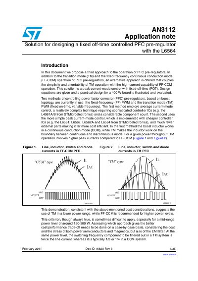
The document proposes a third approach for PFC pre-regulators that combines the simplicity of transition mode (TM) operation with the high-current capability of fixed-frequency continuous conduction mode (FF-CCM). This solution utilizes peak current-mode control with a fixed-off-time (FOT) strategy, which does not require a specialized control IC but rather a simple modification of standard TM PFC controller operation using additional passive parts.
The note details the implementation of line-modulated FOT control using the L6564. It explains that the off-time is determined by the decay time of the ZCD pin voltage, which is made a function of the RMS line voltage through an external circuit involving resistors and capacitors. The document provides design equations for calculating component values to ensure the off-time increases with line voltage, preventing distortion at maximum input voltage.
| ZCD pin clamping level (typical) | 5.7 V |
|---|---|
| ZCD pin triggering threshold (typical) | 0.7 V |
No, it does not need a specialized control IC; it requires just a few additional passive parts and no significant extra cost.
The duration is defined by the time needed for the ZCD voltage to decay from the clamping level (5.7 V) to the triggering threshold (0.7 V).