
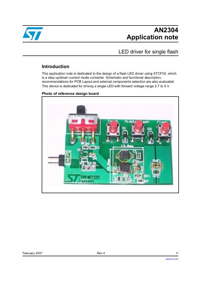
This application note is dedicated to the design of a flash LED driver using STCF02, which is a step-up/down current mode converter. Schematic and functional description, recommendations for PCB Layout and external components selection are also evaluated.
This document provides an application note for designing a flash LED driver circuit based on the STCF02 device. The STCF02 is described as a step-up/down current mode converter capable of operating in five modes: Shutdown, Shutdown with NTC sensing, Torch, Middle Flash, and High Flash. These modes are selected via logic signals connected to enable pins.
The note details the selection of external components required for the circuit, including input/output capacitors, an inductor, resistors for current setting (RFLASH, RTORCH, RMF), and temperature sensing (NTC). It also provides specific PCB design rules, such as using at least four layers, minimizing high-energy switched loops to reduce EMI, and placing components close to the STCF02 chip.
The device is dedicated for driving a single LED with a forward voltage range of 2.7 to 5 V.
The maximum flash LED current for the STCF02 device is 600 mA in a battery voltage range from 2.7 V to 5.5 V.
It is recommended to use a 10 uF/6.3 V ceramic capacitor as the minimum value for both the input and output capacitors.