
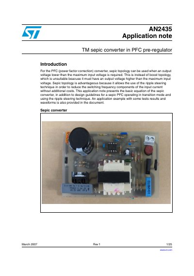
This application note presents the basic equation of the sepic converter, in addition to design guidelines for a sepic PFC operating in transition mode and using the ripple steering technique. An application example with some tests results and waveforms is also provided in the document.
This document describes the application of SEPIC topology for Power Factor Correction (PFC) converters, specifically when an output voltage lower than the maximum input voltage is required. It details the operation of the SEPIC converter, including its advantages over boost topology and the use of ripple steering techniques to reduce switching frequency components in the input current.
The note provides basic equations for the SEPIC converter, design guidelines for operation in transition mode, and a practical design example. It also includes a description of a board used for bench evaluation and presents test results and waveforms to validate the design. This manual is written in Chinese.
The SEPIC topology allows the output voltage to be lower than the maximum input voltage, whereas a boost topology requires the output voltage to be higher than the maximum input voltage.
The break-down voltages are the sum of the input and output voltages, which is higher than the output voltage alone in a boost converter.
The example waveforms show the circuit operating with an input voltage of 230 VAC RMS and an output power of 65 W.