
One way to minimize the size and complexity of a battery charger is to use a linear-type charger. The linear charger drops the AC adapter voltage down to the battery voltage. The number of external components is low: linear chargers require input and output bypass capacitors, and sometimes need an external pass transistor, and resistors for setting voltage and current limits. The main pitfall of a linear charger is power dissipation. The charger simply drops the AC adapter voltage down to the battery voltage. In the case of a 0.8 A charger, a 5 V±10% regulated AC adapter voltage, and battery voltage that varies between 4.2 V and 2.5 V, the power dissipation can range from 0.64 W to 2.0 W. This type of charger is simpler than the switch-mode type, mainly because the passive LC filter is not required. It dissipates the most power when the battery voltage is at its minimum, since the difference between the fixed input voltage and the battery voltage is greatest during this condition.
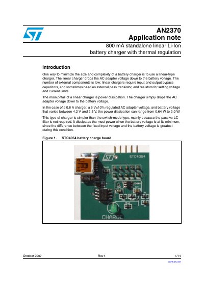
This document describes the STC4054, a constant current/constant voltage charger designed for single-cell Li-Ion batteries. It features a ThinSOT package requiring no external sense resistor or blocking diode, making it ideal for portable applications. The device operates within USB power specifications and includes internal thermal regulation to protect against high power or ambient temperatures.
| Charge Voltage | 4.2 V |
|---|---|
| Max Charge Current | 800 mA |
| Package Type | TSOT23-5L ThinSOT |
| Shutdown Supply Current | 25 uA |
| Input Voltage | 4.25 V |
The charge voltage is fixed at 4.2 V.
The charge current is programmed using a single resistor connected between the PROG pin and GND.
No, no external sense resistor or blocking diode is required.