
This paper describes the functionality and the operation of the STSR2P device used as the secondary synchronous rectifier driver in Forward topology switched mode power supplies. The STSR2P Smart Driver IC provides two complementary high current outputs to drive Power Mosfets. The IC is dedicated to properly drive secondary Synchronous Rectifiers in medium power, low output voltage, high efficiency Forward Converters. From a synchronizing clock input, the IC generates two driving signals with a certain dead time between complementary pulses. The adopted transitions...
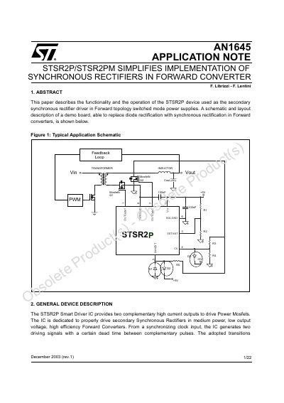
The document details the STSR2P Smart Driver IC, which provides two complementary high current outputs to drive Power MOSFETs in medium power, low output voltage, high efficiency Forward Converters. It explains how the IC generates driving signals with a specific dead time to prevent shoot-through conditions and operates independently of the forward magnetic reset technique.
The note covers pin connections, supply voltage requirements (4V to 5.5V), and synchronization methods. It provides circuit diagrams for synchronizing the IC in both Continuous Conduction Mode (CCM) and Discontinuous Conduction Mode (DCM), including solutions for handling voltage spikes and ringing. Additionally, it describes the INHIBIT operation to allow discontinuous mode by turning off the freewheeling MOSFET when current approaches zero.
| Supply Input Range | 4V to 5.5V |
|---|---|
| Maximum Supply Voltage | 5.7V |
| Maximum CK Pin Current | 10mA |
| Internal Comparator Threshold | -25mV |
| Inhibit Monitoring Time | 250ns |
| Minimum Voltage Difference for DCM | 400mV |
The supply input range is from 4V to 5.5V.
The INHIBIT pin turns off the freewheeling MOSFET when the current approaches zero, allowing the body diode to operate as a common rectifier.
The internal comparator on the INHIBIT pin has a threshold of -25mV.