
This paper presents the operation principle of resonant converters and the two major types. Resonant converters can control the output voltage by changing the frequency, thereby reducing switching losses and electromagnetic interference.
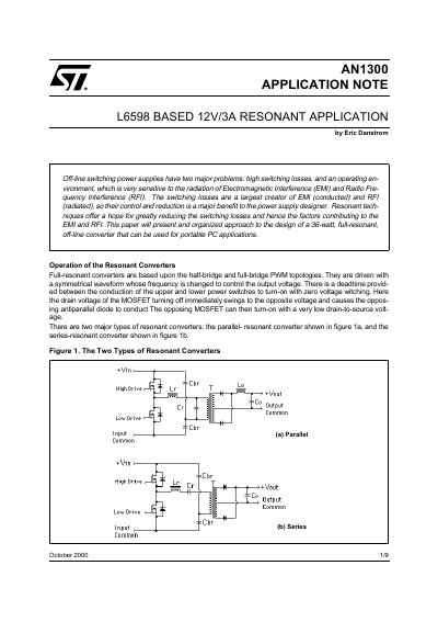
This document describes the operation of full-resonant converters based on half-bridge and full-bridge PWM topologies. It explains how these converters use symmetrical waveforms with variable frequency to control output voltage and achieve zero voltage switching, thereby reducing switching losses and electromagnetic interference (EMI). The text details two major types: parallel-resonant and series-resonant converters, highlighting the differences in load placement and filter requirements.
| Output Voltage | 12 VDC +/- 2% |
|---|---|
| Rated Output Current | 3 A |
| Lightest Output Current | 0.5 A |
| Resonant Frequency | 100 kHz |
| Core Size | EE25/19 |
The two major types are the parallel-resonant converter and the series-resonant converter.
Output power is controlled by changing the frequency of the symmetrical waveform driving the converter.