
This document describes the features and characteristics of the L4981 PFC controller. It is a high performance device operating in average current mode with many on-chip functions. The driver output stage can deliver 1.5A, which is very important for this type of application.
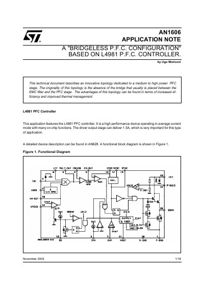
The document details an innovative 'Bridgeless PFC Configuration' designed for medium to high power applications. This topology eliminates the traditional input rectifier bridge, reducing heat dissipation and improving overall system efficiency compared to conventional boost topologies.
The guide explains how to implement this configuration using two PowerMOSFETs (M1 and M2) driven synchronously by the L4981 PFC controller. It covers circuit operation during positive and negative half-cycles, current sensing techniques for high power applications using magnetic transformers, input voltage sensing, and voltage feed-forward circuits.
| Controller Driver Output Current | 1.5A |
|---|---|
| Input Voltage Range (Feed-forward) | 88V to 264V |
| Controller Off-Time Minimum | 5% of period |
The topology offers increased efficiency and improved thermal management by eliminating the input rectifier bridge.
A magnetic current transformer is preferred over a simple resistor to handle the continuously changing current direction and reduce dissipation.