
USB6Bx is a transient overvoltage protector designed to protect sensitive equipment, such as Universal Serial Bus ports, RS-423 interfaces, RS-485 interfaces, ISDN equipment, T1/E1 line cards, and HDSL/ADSL interfaces. The product features a full diode bridge with integrated clamping protection, a breakdown voltage of 6V, peak pulse power dissipation of 500W, and very low capacitance compatible with high data or signal rates.
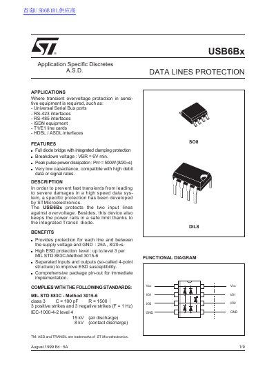
The STMicroelectronics USB6Bx is an application-specific discrete component designed to protect sensitive equipment from transient overvoltage. It features a full diode bridge with integrated clamping protection and an internal Transil diode to keep power rails within safe limits. The device is optimized for high-speed data systems, including Universal Serial Bus (USB) ports, RS-423/RS-485 interfaces, ISDN equipment, and T1/E1 line cards.
| Breakdown voltage (VBR) | 6 V min. |
|---|---|
| Peak pulse power dissipation | 500W (8/20;1s) |
| Leakage current (IRM) | 10 uA |
| ESD protection level (Air discharge) | 15 kV |
It protects Universal Serial Bus ports, RS-423 and RS-485 interfaces, ISDN equipment, T1/E1 line cards, and HDSL/ASDL interfaces.
The device keeps power rails in a safe limit thanks to an integrated Transil diode.
A capacitance of 100nF should be placed between Vcc and ground if connections cannot be short enough.