
This paper introduces the working principle and design method of PFC circuit in detail, and analyzes and discusses the input filtering problem of PFC circuit.
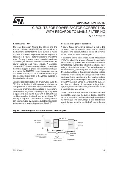
The document explains the principles of active power factor correctors (PFCs) required by European norms to limit harmonic content in mains-supplied equipment. It details how PFCs function as AC-to-DC converters using pulse width modulation to draw sinusoidal current from the mains.
The text analyzes various topologies, recommending the boost configuration for cost optimization due to lower filter requirements and smaller inductors. It provides guidelines on optimizing parameters such as input capacitor values, current ripple, and switching frequency, while also discussing the trade-offs between continuous and discontinuous modes of operation.
| Recommended input capacitor value per kW | 3.3.F/kW |
|---|---|
| Typical inductor value for continuous mode (1A ripple) | 1mH |
| Inductor value for discontinuous mode (6A ripple) | 150,H |
A switching frequency below 50kHz should be used if compliance with VFG243 is required to significantly reduce filter costs.
A value of 3.3 F/kW is considered a good compromise between current distortion and noise generation.
Power MOSFET transistors are practical in applications using up to 277V AC mains with an output power of up to 3kW.