
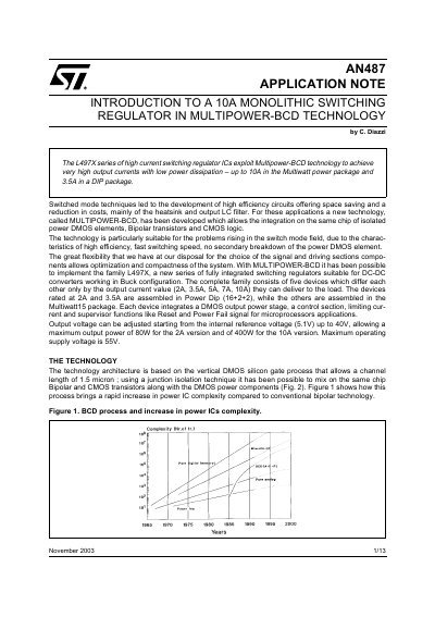
This document introduces the development of high-efficiency circuits using switched mode techniques, which offer space saving and cost reduction, particularly in the heatsink and output LC filter. A new technology called MULTIPOWER-BCD has been developed for these applications, allowing the integration of isolated power DMOS elements, bipolar transistors, and CMOS logic on the same chip. This technology is especially suitable for switch mode applications due to its high efficiency, fast switching speed, and no secondary breakdown of the power DMOS element. With MULTIPOWER-BCD, the L497X family has been implemented, which is a new series of fully integrated switching regulators suitable for DC-DC converters operating in Buck configuration. The family consists of five devices with different output current values (2A, 3.5A, 5A, 7A, 10A). The devices rated at 2A and 3.5A are assembled in Power Dip (16+2+2) package, while the others are assembled in the Multiwatt15 package. Each device integrates a DMOS output power stage, a control section, limiting current, and supervisor functions such as reset and power fail signal for microprocessor applications. The output voltage can be adjusted starting from the internal reference voltage.
This document introduces the L497X series of high current switching regulator ICs, which utilize MULTIPOWER-BCD technology to integrate isolated power DMOS elements, Bipolar transistors, and CMOS logic on a single chip. The series is designed for DC-DC converters in Buck configuration, offering output currents ranging from 2A to 10A.
| Output Current | 2A, 3.5A, 5A, 7A, 10A |
|---|---|
| Output Voltage Range | 5.1V to 40V |
| Maximum Output Power (10A version) | 400W |
| Maximum Operating Supply Voltage | 55V |
| Internal Reference Voltage | 5.1V |
| Reference Voltage Accuracy | +- 2% |
| Internal Power Supply Voltage | 12V |
| Soft Start Charge Current | 100uA |
| UnderVoltage Lockout Threshold | 11V |
| Error Amplifier Transconductance | 4mA/V |
The L497X series exploits MULTIPOWER-BCD technology to achieve very high output currents with low power dissipation.
The maximum output power for the 10A version is 400W.
The internal reference voltage is 5.1V, which is accurate within +- 2% limits.
The under voltage lockout keeps the power output stage off until Vcc reaches 11V.