
STMicroelectronics AN2526 STMAV340 Evaluation Board Guide

This application note describes the STMAV340 evaluation board design and features, as well as the PCB layout.

STMicroelectronics AN2526 STMAV340 Evaluation Board Guide - cover page
Brand
STMicroelectronics
Category
Other Electronics
Document type
Application Note
Language
English
Pages
10
File format
PDF
File size
174 KB
Published
06 August, 2012
Updated
30 September, 2023
MD5 checksum
FF18057007B2AAE359C8859B21777D0E

About this manual

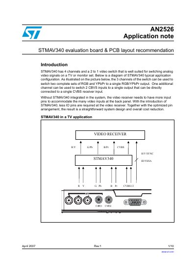
This document describes the STMAV340 evaluation board, which is designed to facilitate customer testing of the STMAV340 video switch. The board supports two sets of RGB and YPbPr inputs, switching them to a single output, and includes provisions for CVBS inputs. It details the power supply requirements, video port configurations, and digital control signal connections.

What's inside

  • Evaluation board
  • PCB layout recommendation
  • Revision history
  • Power supply
  • Video input & output ports
  • Video inputs conditioning
  • Digital control signals
  • Bill of materials

Specifications

Input voltage (DC adaptor)7 to 15 V
Blanking level range0 V to 2.5 V
Number of video channels4 channels
Video switch function2 to 1 video switch

Frequently asked questions

What is the recommended power supply voltage for the DC adaptor?

The DC adaptor should have an output voltage of 7 V to 15 V.

How many video input ports does the evaluation board have?

The board has four video input ports: VGA1, VGA2, CVBS1, and CVBS2.

What is the maximum blanking level the board can handle?

The board can handle video signals with a blanking level of 0 V to 2.5 V.

Download PDF (174 KB)

More STMicroelectronics Manuals


View all STMicroelectronics manuals →