
This document describes the reference design of the 25W Switch Mode Power Supply which is dedicated to industrial or white goods applications. The board accepts wide range input voltages (90 to 265Vrms) and delivers 2 or 3 output voltages depending on the version. Two types of power supply are available: negative output or positive output voltage. The actual version depends the way the components are assembled on the secondary side and on the configuration of jumpers. On the primary side, the PCB and transformer are the same for both versions. More information is available in Chapter 3. The Switch mode power supply is based on the VIPer53E. The VIPer53E combines in the same package an enhanced current mode PWM controller with a high voltage MDMesh Power Mosfet. High efficiency and low standby consumption are the main characteristics of this board. Such features, coupled with minimal part requirements and global low cost in addition to, makes it an ideal solution for powering industrial or consumer equipment, meeting worldwide standards.
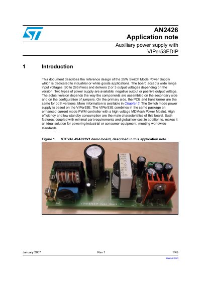
This document details the reference design of a 25W Switch Mode Power Supply (SMPS) dedicated to industrial or white goods applications. The design is based on the VIPer53E, which integrates an enhanced current mode PWM controller with a high voltage MDMesh Power Mosfet in a single package. The board accepts a wide input voltage range of 90 to 265Vrms and delivers 2 or 3 output voltages depending on the specific version configuration.
| Input voltage | 90-265Vrms |
|---|---|
| Frequency | 45-66Hz |
| Standby consumption | <1 Watt |
| EMI standard | EN55022 Class B |
| Output voltages (Positive) | 3.3V/100mA, 5V/3A, 12V/0.8A |
| Output voltages (Negative) | -5V/3A, -12V/0.8A |
The board accepts a wide range of input voltages from 90 to 265Vrms.
The standby consumption is less than 1 Watt.
The design complies with EMI according to EN55022 Class B.