
The A3968SA and A3968SLB are designed to bidirectionally control two dc motors. Each device includes two H-bridges capable of continuous output currents of ±650 mA and operating voltages to 30 V. Motor winding current can be controlled by the internal fixed-frequency, pulse-width modulated (PWM), current-control circuitry. The peak load current limit is set by the user’s selection of a reference voltage and current-sensing resistors. Except for package style and pinout, the two devices are identical. The fixed-frequency pulse duration is set by a user-selected external RC timing network. The capacitor in the RC timing network also determines a user-selectable blanking window that prevents false triggering of the PWM current-control circuitry during switching transitions. To reduce on-chip power dissipation, the H-bridge power outputs have been optimized for low saturation voltages. The sink drivers feature the Allegro® patented Satlington® output structure. The Satlington outputs combine the low voltage drop of a saturated transistor and the high peak current capability of a Darlington. For each bridge, the INPUTA and INPUTB terminals determine the load current polarity by enabling the appropriate source and sink driver pair. When a logic low is applied to both INPUTs of a bridge, the braking function is enabled. In brake mode, both source drivers are turned OFF and both sink drivers are turned ON, thereby dynamically braking.
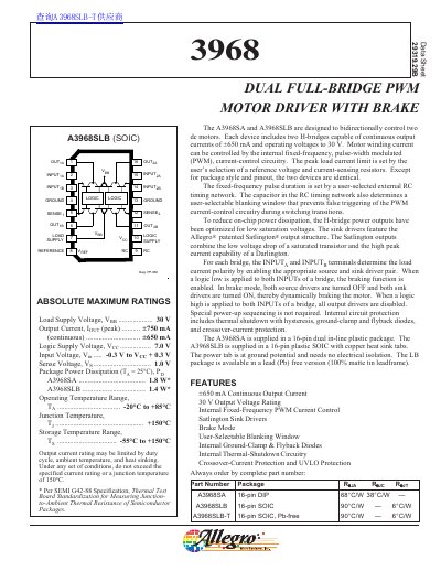
The A3968SA and A3968SLB are dual full-bridge PWM motor drivers designed to bidirectionally control two DC motors. Each device includes two H-bridges capable of continuous output currents of +650 mA and operating voltages up to 30 V. Motor winding current is controlled by internal fixed-frequency, pulse-width modulated (PWM) current-control circuitry.
| Continuous Output Current | +650 mA |
|---|---|
| Output Voltage Rating | 30 V |
The device supports operating voltages up to 30 V.
Brake mode is enabled when a logic low is applied to both INPUT terminals of a bridge, turning off source drivers and turning on sink drivers.