
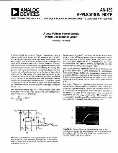
Analog Devices AN-139 Application Note Low-Voltage Power Supply Watch-Dog Monitor Circuit


Analog Devices AN-139 Application Note Low-Voltage Power Supply Watch-Dog Monitor Circuit - cover page
Brand
Analog Devices
Category
Other Electronics
Document type
Application Note
Language
English
Pages
2
File format
PDF
File size
106 KB
Published
03 August, 2012
Updated
30 August, 2012
MD5 checksum
7A73A62C646F3636436B6B60C675A868

About this manual

The document presents a simple circuit consisting of a reference diode and a matched PNP transistor pair (MAT-03) designed to monitor low voltage power rails, such as +5V logic supplies. This circuit is intended for use in microprocessor-based systems utilizing battery-backed-up CMOS or EEPROM memory.

What's inside

  • A Low-Voltage Power Supply Watch-Dog Monitor Circuit
  • Circuit Description and Operation
  • Trip-Point Voltage Calculation
  • Response Time Characteristics
  • Hysteresis Implementation
  • Active LOW Output Modification
  • MAT-01 Transistor Pair Application

Specifications

Response time700ns
Minimum supply voltage for accurate output1.7V

Frequently asked questions

What components are used in the basic monitor circuit?

The circuit consists of a reference diode and a matched PNP transistor pair, specifically the MAT-03.

What is the purpose of this monitor circuit?

It prevents inadvertent writing to memory as the rest of the digital circuitry turns off with a falling +5V supply.

Download PDF (106 KB)

More Analog Devices Manuals


View all Analog Devices manuals →