
AN-762 is an application note about ADN2891 evaluation board. ADN2891 is a data quantizer for SONET, Gigabit Ethernet (GbE) and Fibre Channel optical receivers, supporting a signal data rate from a minimum of 155 Mbps up to a maximum of 3.2 Gbps. ADN2891 has a better than 4mV p-p typical input sensitivity and works well with input level up to 2 V p-p. ADN2891 also provides loss of signal (LOS) and received signal strength indicator (RSSI) features, which makes ADN2891 an ideal limiting amplifier for all SFF-8472-compliant SFP transceivers.
The document provides an overview of the ADN2891 limiting amplifier and its associated evaluation board. The chip functions as a data quantizer supporting signal data rates from 155 Mbps up to 3.2 Gbps, suitable for SFF-8472-compliant SFP transceivers. It features input sensitivity better than 4mV p-p and includes Loss of Signal (LOS) and Received Signal Strength Indicator (RSSI) functions.
| Signal Data Rate Support | 155 Mbps to 3.2 Gbps |
|---|---|
| Input Sensitivity | Better than 4mV p-p typical |
| Power Supply Voltage | 3.3 V |
| Transmission Line Impedance | 50 ohm |
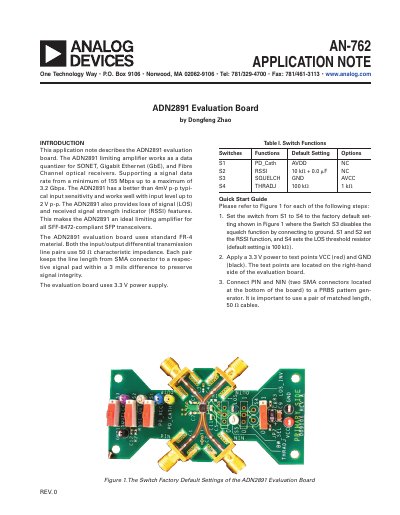
The factory default setting for Switch S4 is a resistor value of 100 kΩ.
The ADN2891 provides CML (Current Mode Logic) outputs.
The threshold is set by selecting a resistor value between the THRADJ pin and GND using Switch S4.