
1N4001S-1N4007S are 1.0 amp silicon rectifiers with low forward voltage drop, high current, high reliability, high surge current capability, plastic molded case, UL 94V-0 rated flame retardant epoxy, axial leads, soldered per MIL-STD-202, method 208 guaranteed polarity, color band denotes cathode end, any mounting position, weight 0.34 grams.
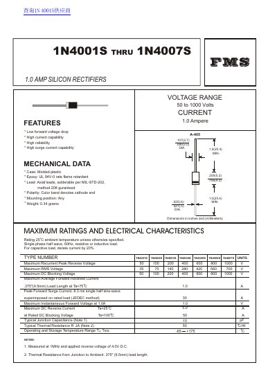
This document provides technical specifications for the FMS 1N4001S through 1N4007S series of 1.0 Amp silicon rectifiers. Key features include low forward voltage drop, high current capability, and high reliability with a molded plastic case.
| Current | 1.0 Ampere |
|---|---|
| Voltage Range | 50 to 1000 Volts |
| Case Material | Molded plastic |
| Epoxy Rating | UL 94V-0 |
| Weight | 0.34 grams |
| Operating Temperature Range | -65 to +175 C |
| Peak Forward Surge Current | 30 A |
The maximum average forward rectified current is 1.0 A.
The typical junction capacitance is 15 pF.
The typical thermal resistance is 50 C/W.