
Analog Devices uC001 MicroConverter I2C Compatible Interface Technical Note

This document introduces the hardware slave and software master implementation of the I2C interface
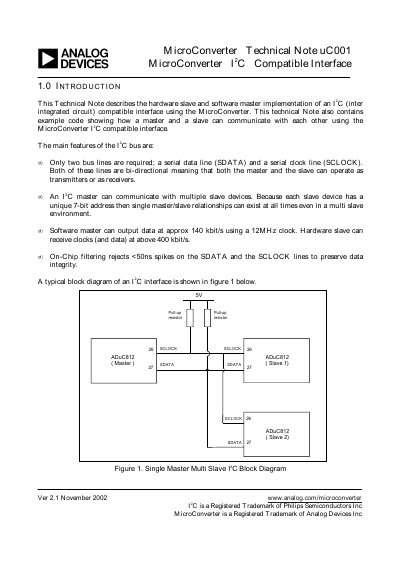

Analog Devices uC001 MicroConverter I2C Compatible Interface Technical Note - cover page
Brand
Analog Devices
Document type
Application Note
Language
English
Pages
27
File format
PDF
File size
126 KB
Published
03 August, 2012
Updated
30 September, 2023
MD5 checksum
D95308777D6D06CD971235BC4DACFF6F

About this manual

This document is a technical note (uC001) from November 2002 that describes how to implement an I2C compatible interface using the MicroConverter. It covers both hardware slave mode and software master mode implementations.

The guide details the I2C data transfer sequence, including start/stop conditions, addressing, and acknowledge signals. It specifies that the MicroConverter provides a hardware slave capable of receiving clocks above 400 kbit/s and a software master capable of outputting data at approximately 140 kbit/s using a 12MHz clock.

What's inside

  • Introduction
  • I2C Interface Overview
  • Complete Data Transfer Sequence
  • Slave Addressing
  • Implementation on the MicroConverter

Frequently asked questions

What is the maximum data output rate for a software master using a 12MHz clock?

A software master can output data at approximately 140 kbit/s when using a 12MHz clock.

What is the minimum clock speed required for the hardware slave to receive data?

The hardware slave can receive clocks and data at speeds above 400 kbit/s.

What is the default value for the I2CADD register that holds the MicroConverter's address?

The default value for the I2CADD register, which holds the device address, is 55H.

Download PDF (126 KB)

More Analog Devices Manuals


View all Analog Devices manuals →