
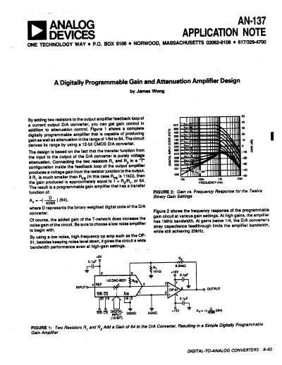
The document details a circuit design that adds two resistors to the output amplifier feedback loop of a current output D/A converter. This configuration allows for both gain control and attenuation control, achieving a range from 1/64 to 64 using a 12-bit CMOS D/A converter.
The design utilizes a low noise, high-frequency operational amplifier, such as the OP-61, to maintain wide bandwidth performance even at high-gain settings. The note includes circuit diagrams and frequency response data showing that the amplifier achieves 1MHz bandwidth at high gains.
| Programmable Range | 1/64 to 64 |
|---|---|
| D/A Converter Resolution | 12-bit CMOS |
| High Gain Bandwidth | 1MHz |
| Low Gain Bandwidth | 20kHz |
The design requires adding two resistors to the output amplifier feedback loop of a current output D/A converter.
The text recommends using a low noise, high-frequency op amp such as the OP-61.
Gain is produced by connecting two resistors in a T-network configuration inside the feedback loop of the output amplifier.