
The PM100RLA120 is a three-phase 100A, 1200V intelligent power module that uses a fifth-generation IGBT chip that provides improved performance with a typical Vce(sat) of 1.9V at Tj=125°C. It also features CSTBT chip over-temperature protection and error output from both the upper and lower arms of the IPM. The current rating for the braking portion has been increased by 50% of the inverter current rating. The module also provides acoustic noise elimination, 18.5kW/22kW class inverter application, and UL recognized yellow card number E80276(N), file number E80271.
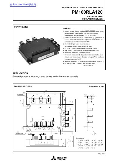
This document is a technical datasheet for the Mitsubishi Electric PM100RLA120, a flat-base type insulated Intelligent Power Module (IPM). The device utilizes a new 5th generation CSTBT chip to improve performance, offering typical collector-emitter saturation voltages of 1.9V at 125°C. It is designed for general-purpose inverters, servo drives, and motor controls, supporting up to 18.5kW/22kW class applications with acoustic noise-less operation.
| Collector Current (Brake) | 50 A |
|---|---|
| Junction Temperature Range | -20 ~ +150 °C |
| Weight | 800 g |
It adopts a new 5th generation IGBT (CSTBT) chip with a 1µm fine rule process.
The typical Vce(sat) is 1.9V when the junction temperature is 125°C.
The recommended supply voltage applied across P-N terminals should be less than 800 V.