
The R1225N Series are CMOS-based PWM step-down DC/DC Converter controllers with low supply current. Each of these ICs consists of an oscillator, a PWM control circuit, a reference voltage unit, an error amplifier, a soft-start circuit, a latch-type protection circuit, a PWM/VFM alternative circuit, a chip enable circuit, a phase compensation circuit, and an input voltage detect circuit. Further, protection circuit delay time adjuster circuit, and resistors for voltage detection are included. A low ripple, high efficiency step-down DC/DC converter can be easily composed of this IC with some external components, or a power-transistor, an inductor, a diode and capacitors.
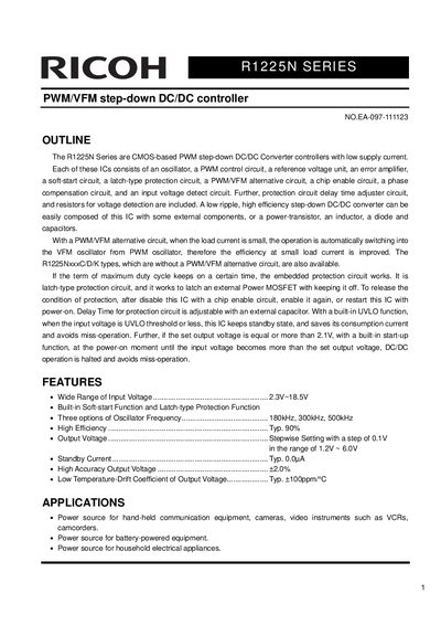
The R1225N Series are CMOS-based PWM step-down DC/DC Converter controllers designed for low supply current applications. Each IC integrates an oscillator, PWM control circuit, reference voltage unit, error amplifier, soft-start circuit, latch-type protection circuit, and a PWM/VFM alternative circuit to improve efficiency at small load currents. The series is available with various oscillator frequencies (180kHz, 300kHz, 500kHz) and includes options without the PWM/VFM alternative circuit.
The document provides detailed electrical characteristics, absolute maximum ratings, and application hints for designing power source circuits for hand-held communication equipment, cameras, and battery-powered devices. It specifies the pin configuration for the SOT-23-6W package and includes equations for calculating the protection circuit delay time using an external capacitor.
| Operating Input Voltage | 2.3V ~ 18.5V |
|---|---|
| Output Voltage Range | 1.2V ~ 6.0V |
| Output Voltage Accuracy | Typ. 2.0% |
| Standby Current | Typ. 0.0uA |
| Operating Temperature Range | -40 ~ +85 °C |
| Package Type | SOT-23-6W |
When the load current is small, the operation automatically switches from the PWM oscillator to the VFM oscillator to improve efficiency at small load currents.
The delay time for the protection circuit is adjustable with an external capacitor connected to the DLY pin.
The embedded latch-type protection circuit works to latch an external Power MOSFET with keeping it off.
The minimum operating input voltage is 2.3V.