
RP550K001A is a CMOS-based 1A* dual step-down DC/DC converter with synchronous rectifier. Internally, each converter consists of oscillators, reference voltage units, error amplifiers, switching control circuits, soft-start circuit, latch type protection circuit, an under voltage lockout (UVLO) circuit, a thermal shutdown circuit and switching transistors. By adopting a synchronous rectifier with built-in switching transistors, a low ripple high efficiency synchronous rectifier step-down DC/DC converter can be easily configured with simply using two inductors, resistors and capacitors as the external components. RP550K001A is available in DFN(PLP)2730-12 package which achieves high-density mounting on boards. Output voltage is adjustable with external divider resistors. Latch type protection circuit latches the built-in driver to the OFF state during high load or if the output is short-circuited for a specified time (protection delay time). The latch type protection circuit can be released by once setting the converter into the standby mode with the CE pin and then setting it back to the active mode, or, by turning the power off and back on. Setting the supply voltage lower than the UVLO detector threshold can also release the latch type protection circuit. Thermal shutdown circuit detects overheating of the converter and stops the converter operation to protect it from damage.
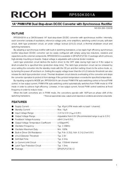
The Ricoh RP550K001A is a CMOS-based 1A dual step-down DC/DC converter with a built-in synchronous rectifier. It is designed to provide high-density mounting and high efficiency, suitable for powering portable communication equipment, camcorders, and notebook PCs. The device operates with an input voltage range of 2.3V to 5.5V and features adjustable output voltage from 0.6V to 3.3V.
| Output Current | 1A |
|---|---|
| Supply Current (Typ) | 45uA |
| Input Voltage Range | 2.3V to 5.5V |
| Output Voltage Range | 0.6V to 3.3V |
| Oscillator Frequency | 2.25MHz |
| Package | DFN(PLP)2730-12 |
| Operating Temperature | -40 to +85 °C |
The recommended output voltage range is from 0.6V to 3.3V.
Setting the MODE pin to 'H' enables Forced PWM Control, while 'L' enables PWM/VFM Auto Switching Control.