
The RP502x Series are low supply current CMOS-based PWM/VFM step-down DC/DC converters with synchronous rectifier. RP502x can be selected from two control types - fixed PWM control or PWM/VFM auto switching control in which mode automatically switches to high-efficiency VFM mode in low output current. RP502x includes a soft start circuit, an under-voltage lockout circuit (UVLO), and a latch protection circuit. By simply using an inductor and capacitors as external components, a high-efficiency step-down DC/DC converter can be easily configured. The small inductor (1.0μH/2.2μH) and small output capacitor (4.7μF) can be used by the switching of 3.3MHz.
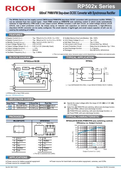
The Ricoh RP502x Series consists of CMOS-based step-down DC/DC converters with a synchronous rectifier. Each IC integrates an oscillator, reference voltage unit, error amplifier, switching control circuit, soft-start circuit, protection circuits, UVLO circuit and switching transistors. The current-limit circuit controls the peak Lx current at each clock cycle, and the latch protection turns the built-in driver off if load current exceeds the limit for a certain period.
The output voltage is fixed with built-in feedback resistance and is adjustable in 0.1V steps with ±1.5% or ±24mV accuracy. The devices are available in WLCSP-6-P2 and DFN1616-6 packages and have PWM/VFM auto switching or PWM fixed switching modes. Applications include battery-powered equipment, hand-held communication equipment, cameras, VCRs, camcorders, HDDs and portable equipment.
| Input voltage range for VOUT ≥ 1.0V | 2.5V to 5.5V |
|---|---|
| Input voltage range for VOUT < 1.0V | 2.5V to 4.5V |
| Output voltage range | 0.8V to 3.3V in 0.1V steps |
| Supply current | Typ. 750uA at normal |
| Oscillator frequency | Typ. 3.3MHz |
| Absolute maximum ratings | 6.0V |
| Packages | WLCSP-6-P2, DFN1616-6 |
| Soft start time | Typ. 0.12ms |
| UVLO detector threshold | Typ. 2.2V |
| Operating temperature range | -40 to 85 °C |
It supports 2.5V to 5.5V for VOUT of 1.0V or higher, and 2.5V to 4.5V for VOUT below 1.0V.
The available packages are WLCSP-6-P2 and DFN1616-6.
The oscillator frequency is typically 3.3MHz.
Disable the ICs with a chip enable circuit and then enable it again, or make the power supply voltage lower than UVLO.