
R2062 SERIES 3 wire interface Real-Time Clock ICs with Battery Backup switch-over Function
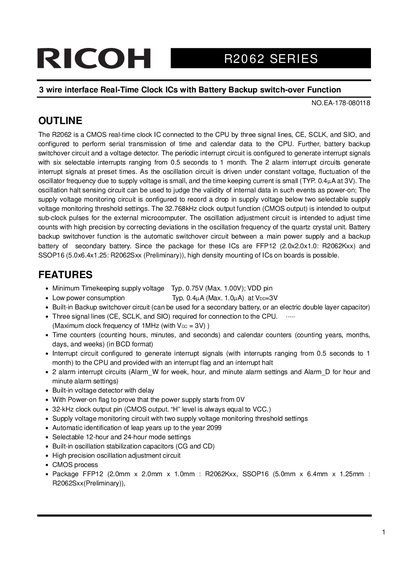
The Ricoh R2062 series consists of CMOS real-time clock ICs designed to connect to a CPU via three signal lines: CE, SCLK, and SIO. These devices perform serial transmission of time and calendar data and include a battery backup switchover circuit and a voltage detector. The series supports periodic and alarm interrupt circuits, with the oscillation circuit driven under constant voltage to minimize frequency fluctuation and power consumption.
| Timekeeping supply voltage (Typ.) | 0.75V |
|---|---|
| Timekeeping supply voltage (Max.) | 1.00V |
| Time keeping current (Typ.) | 0.4uA |
| Maximum clock frequency | 1MHz |
| Operating temperature range | -40 to +85 °C |
| Storage temperature range | -55 to +125 °C |
| Package types | FFP12, SSOP 16 |
It is an automatic switchover circuit between a main power supply and a backup battery of a secondary battery.
Three signal lines are required: CE, SCLK, and SIO.
The maximum clock frequency is 1MHz when Vcc is 3V.