
This document introduces the programming specifications for PIC12C67X and PIC12CE67X, including hardware requirements, programming mode, program mode entry, program memory programming, etc.
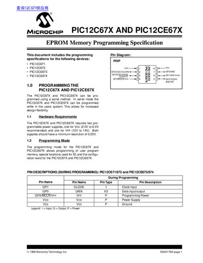
This document provides the programming specifications for the PIC12C67X and PIC12CE67X families of EPROM memory devices. It details the serial method required to program user program memory, special ID locations, and configuration words while the device is in the user's system.
The guide outlines hardware requirements, including specific voltage levels for VDD (2.0V to 6.0V) and VPP (12V to 14V). It describes the Program/Verify mode entry sequence, pin descriptions during programming, and the memory map implementation. Additionally, it lists available commands such as Load Configuration, Load Data, Read Data, Increment Address, Begin Programming, and End Programming.
| VDD Operating Range | 2.0V to 6.0V recommended |
|---|---|
| VPP Programming Voltage | 12V to 14V |
| Power Supply Resolution | 0.25V minimum |
| User Program Memory Size (PIC12C671) | 1K words |
The recommended operating range for VDD is 2.0V to 6.0V.
The required voltage range for VPP is 12V to 14V.
Sixteen cycles are applied to the clock pin when loading a 14-bit data word.