
The ADG1206 and ADG1207 are monolithic iCMOS analog multiplexers comprising sixteen single channels and eight differential channels, respectively. These devices feature extremely low switch capacitance and switch resistance and are suitable for a wide variety of applications including audio and video routing, automatic test equipment, data acquisition systems, battery-powered systems, sample-and-hold systems, and communication systems.
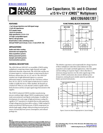
The ADG1206 and ADG1207 are monolithic iCMOS analog multiplexers designed for high-performance data acquisition and sample-and-hold systems. The ADG1206 switches one of sixteen inputs to a common output using 4-bit binary address lines, while the ADG1207 handles eight differential channels with 3-bit addressing. Both devices feature an EN input to enable or disable operation.
Constructed using high voltage CMOS and bipolar technologies, these multiplexers support up to 33 V supply ranges. Key features include less than 1 pC charge injection, 1.5 pF off capacitance for the ADG1206, and break-before-make switching action. They are available in 28-lead TSSOP and 32-lead LFCSP_VQ packages.
| On Resistance, Ron | 120 Ω typ / 240 Ω max |
|---|---|
| Charge Injection | <1 pC |
| Off Capacitance (ADG1206) | 1.5 pF typ |
| Supply Range | 33 V |
The maximum on-resistance is 270 Ω when the supply voltage is +13.5 V.
The minimum break-before-make time delay is 10 ns under specified test conditions.