
Mimix Broadband's 34.0-46.0 GHz GaAs MMIC fundamental image reject mixer can be used as an up- or down-converter. The device has a conversion loss of 7.0 dB with a 20.0 dB image rejection across the band. I and Q mixer outputs are provided and an external 90 degree hybrid is required to select the desired sideband. This MMIC uses Mimix Broadband's 0.15 µm GaAs PHEMT device model technology, and is based upon electron beam lithography to ensure high repeatability and uniformity. The chip has surface passivation to protect and provide a rugged part with backside via holes and gold metallization to allow either a conductive epoxy or eutectic solder die attach process. This device is well suited for Millimeter-wave Point-to-Point Radio, LMDS, SATCOM and VSAT applications.
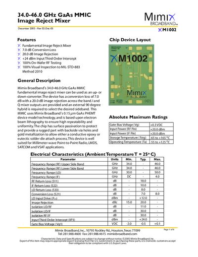
The document describes the Mimix Broadband XM1002, a Gallium Arsenide (GaAs) MMIC designed as an up- or down-converter for millimeter-wave applications such as LMDS and VSAT. It features a conversion loss of 7.0 dB and provides Q mixer outputs that require an external 90-degree hybrid to select the desired sideband.
The datasheet includes absolute maximum ratings, electrical characteristics tables, graphical performance data for conversion gain and image rejection across the frequency band, mechanical drawings with bond pad definitions, and application notes regarding biasing and USB/LSB selection methods.
| Frequency Range (RF) | 34.0 - 46.0 GHz |
|---|---|
| Frequency Range (LO) | 30.0 - 50.0 GHz |
| Conversion Loss | 7.0 dB |
| Image Rejection | 20.0 dB |
| Input Third Order Intercept (IIP3) | +24 dBm |
| Gate Bias Voltage (Vg1) | -0.5 VDC |
The device should be operated with a gate voltage of -0.5 VDC to achieve optimum conversion loss.
The device operates within a frequency range of 34.0 to 46.0 GHz.
The mixer has a typical conversion loss of 7.0 dB.
You should set the gate voltage Vg1 to -0.5V.