
This document describes the electrical performance, frequency range, package size, supply voltage, output type, temperature stability, aging, and other characteristics of Vectron International's Crystal Clock Oscillators (XO’s) products.
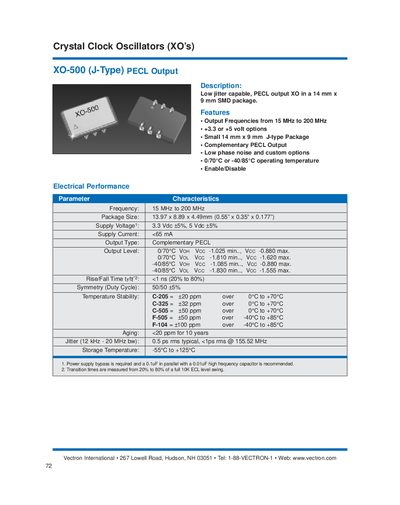
The XO‑500 is a crystal clock oscillator with a 14 mm × 9 mm J‑type SMD package. It offers complementary PECL output and selectable supply voltages of 3.3 V or 5 V, making it suitable for high‑speed digital designs that require low phase noise and precise timing.
Key electrical characteristics include a frequency range of 15 MHz‑200 MHz, supply current under 65 mA, rise/fall time under 1 ns, and jitter as low as 0.5 ps rms typical. The device operates from –40 °C to +85 °C (or 0 °C‑70 °C for the standard version) and includes an enable/disable pin for output control.
| Frequency range | 15 MHz to 200 MHz |
|---|---|
| Package size | 13.97 × 8.89 × 4.49 mm |
| Supply voltage options | 3.3 V or 5 V |
| Supply current | < 65 mA |
| Output type | Complementary PECL |
| Rise/Fall time | < 1 ns (20‑80%) |
| Duty‑cycle symmetry | 50 % ± 5 % |
| Jitter (12 kHz‑20 MHz BW) | 0.5 ps rms typical, < 1 ps rms @ 155.52 MHz |
| Aging | < 20 ppm for 10 years |
| Storage temperature | -65 °C to +125 °C |
The XO‑500 provides a complementary PECL output.
It can be powered from either 3.3 V or 5 V supply.
Set pin 1 high to disable the outputs; the output on pin 4 is held low while the complementary output on pin 5 is held high.
Typical jitter is 0.5 ps rms, and it is less than 1 ps rms at 155.52 MHz.