
This is a document describing the LCX033AK product. The product is a 1.1cm (0.44 Type) NTSC/PAL color LCD panel. The panel uses polycrystalline silicon super thin film transistors with built-in peripheral driving circuit and supports full-color display in NTSC/PAL mode. RGB dots are arranged in a delta pattern for high picture quality.
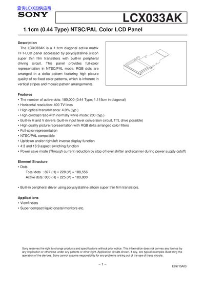
The Sony LCX033AK is a 1.1 cm (0.44 in) diagonal active‑matrix TFT‑LCD panel with built‑in peripheral drivers. It offers full‑color NTSC/PAL representation, a delta‑pattern RGB filter, and functions such as up/down inversion, aspect‑ratio switching (4:3 and 16:9), and power‑save mode.
The document lists electrical characteristics (supply voltages 11.4‑14 V, input voltage ranges, Vth values), pin assignments, timing specifications, and detailed handling precautions to avoid static damage, dust, and mechanical stress.
| Diagonal size | 1.1 cm (0.44 in) |
|---|---|
| Active dots | 180,000 |
| Horizontal resolution | 400 TV lines |
| Optical transmittance (typ.) | 4.0 % |
| Contrast ratio (typ.) | 200 |
| Supply voltage (Vop) | 11.4 V to 14.0 V |
| Operating temperature range | -10 °C to +70 °C |
The panel can operate from –10 °C up to +70 °C.
It has 180,000 active dots (800 H × 225 V).
Use non‑chargeable gloves or bare hands, wear an earth‑band, avoid touching electrodes, and work on a conductive mat.
The driver supply voltage (Vop) must be between 11.4 V and 14.0 V.