
The MAX114/MAX118 are microprocessor-compatible, 8-bit, 4-channel and 8-channel analog-to-digital converters (ADCs). They operate from a single +5V supply and use a half-flash technique to achieve a 660ns conversion time (1Msps). A power-down (PWRDN) pin reduces current consumption typically to 1µA. The devices return from power-down mode to normal operating mode in less than 200ns, allowing large supply-current reductions in burst-mode applications (in burst mode, the ADC wakes up from a low-power state at specified intervals to sample the analog input signals). Both converters include a track/hold, enabling the ADC to digitize fast analog signals. Microprocessor (µP) interfaces are simplified because the ADC can appear as a memory location or I/O port without external interface logic. The data outputs use latched, three-state buffer circuitry for direct connection to an 8-bit parallel µP data bus or system input port. The MAX114/MAX118 input/reference configuration enables ratiometric operation. The 4-channel MAX114 is available in a 24-pin DIP or SSOP. The 8-channel MAX118 is available in a 28-pin DIP or SSOP. For +3V applications, refer to the MAX113/MAX117 data sheet.
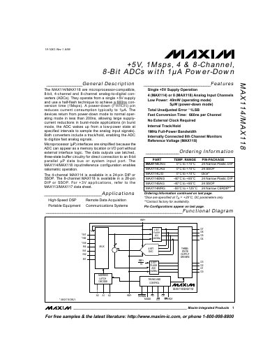
The MAX114 and MAX118 are microprocessor‑compatible 8‑bit analog‑to‑digital converters that operate from a single +5 V supply. They feature a half‑flash conversion technique achieving a 660 ns conversion time (1 Msps) and include an internal track/hold circuit for fast signal digitization.
Both devices offer low‑power operation with a typical power‑down current of 1 µA and provide 4 (MAX114) or 8 (MAX118) analog input channels in 24‑pin DIP/SSOP or 28‑pin DIP/SSOP packages. Detailed electrical, timing, and pin specifications are provided for system integration.
| Supply Voltage | +5 V (single supply) |
|---|---|
| Conversion Time | 660 ns (1 Msps) |
| Power‑Down Current | Typical 1 µA |
| Typical Power Consumption (operating mode) | 40 mW |
| Typical Power Consumption (power‑down mode) | 5 µW |
| Total Unadjusted Error | ≤ 1 LSB |
The typical power‑down current is 1 µA when the PWRDN pin is low.
The MAX118 provides eight analog input channels.
They achieve a conversion time of 660 ns, corresponding to a 1 Msps sampling rate.