
This document introduces the features of the TL284xB and TL384xB series of high-performance current-mode PWM controllers, including low start-up current, trimmed oscillator discharge current, current mode operation up to 500 kHz, automatic feed-forward compensation, latching PWM for cycle-by-cycle current limiting, internally trimmed reference with undervoltage lockout, high-current totem-pole output undervoltage lockout with hysteresis, and double-pulse suppression.
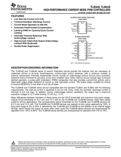
The TL284xB and TL384xB series are high‑performance current‑mode PWM controller ICs that integrate undervoltage lockout, a precision reference, and a totem‑pole output stage suitable for driving N‑channel MOSFETs. They are pin‑compatible with the earlier TL284/TL384 families and offer low start‑up current, trimmed oscillator discharge current, and selectable duty‑cycle ranges. The devices are offered in SOIC (D) and PDIP (P) packages and are targeted at off‑line and DC‑to‑DC applications.
The datasheet lists absolute maximum ratings, recommended operating conditions, and detailed electrical characteristics for each functional block, including the oscillator, error‑amplifier, current‑sense, output, UVLO, and PWM sections. Ordering information, land‑pattern drawings, and an important notice about warranty and safety‑critical use are also included.
| Typical UVLO thresholds (TLx842B/TLx844B) | 16 V (on), 10 V (off) |
|---|---|
| Operating temperature range (TL284xB) | -40 °C to 85 °C |
| Operating temperature range (TL384xB) | 0 °C to 70 °C |
| Package types | SOIC (D) or PDIP (P) |
| Oscillator discharge current (typical) | 8.3 mA |
| Duty‑cycle range (TLx844B/TLx845B) | 0 % to 50 % |
Typical UVLO thresholds are 16 V when on and 10 V when off.