
The MAX354/MAX355 fault-protected multiplexers (muxes) use a series N-channel, P-channel, N-channel structure that protects the devices from overvoltage up to 40V beyond the supply rails during power-up, power-down, and fault conditions. The MAX354/MAX355 also protect sensitive circuit components against voltages near or beyond the normal supplies. The MAX354 single 8-channel mux and the MAX355 dual 4-channel mux protect analog signals while oper- ating from a single 4.5V to 36V supply or ±4.5V to ±18V dual supplies. These muxes have 350Ω on-resistance and can be used for demultiplexing as well as multi- plexing. Input leakage current is less than 0.5nA at +25°C and less than 5nA at +85°C. All digital inputs have 0.8V and 2.4V logic thresholds, ensuring both TTL and CMOS logic compatibility with- out pull-up resistors. Break-before-make operation is guaranteed and power consumption is less than 1.5mW.
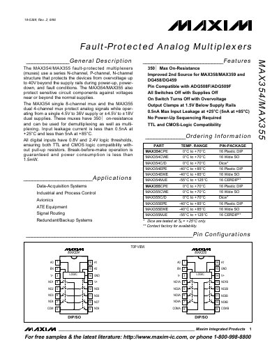
The MAX354 (single 8‑channel) and MAX355 (dual 4‑channel) are fault‑protected analog multiplexers that operate from a single 4.5 V – 36 V supply or ±4.5 V – ±18 V dual supplies. They feature a 350 Ω on‑resistance, input leakage below 0.5 nA at 25 °C, and break‑before‑make switching.
The devices protect against over‑voltage up to 40 V beyond the supply rails, clamp outputs about 1.5 V below the rails, and are compatible with both TTL and CMOS logic levels (0.8 V – 2.4 V thresholds) without external pull‑up resistors. Detailed electrical characteristics, timing diagrams and pin configurations are provided.
| On‑Resistance (RON) | 350 Ω |
|---|---|
| Input Leakage Current (25 °C) | < 0.5 nA |
| Power Consumption | < 1.5 mW |
| Logic Input Thresholds | 0.8 V low, 2.4 V high |
| Break‑Before‑Make Operation | Guaranteed |
The devices protect against over‑voltage up to 40 V beyond the supply rails.
The MAX354 is an 8‑channel multiplexer.
The channel‑to‑channel switching time is typically 180 ns.
The output clamps at approximately 1.5 V below the supply rails.