
The MAX4699/MAX4701/MAX4702 are low-voltage, single-supply CMOS analog switches. MAX4699/MAX4701 are dual double-pole/double-throw (DPDT) switches with two control inputs that control two single-pole/double-throw (SPDT) switches each. MAX4702 is a quad SPDT switch with one control input and one low-voltage digital logic power supply. These devices operate from a single +1.8V to +5.5V power supply. When powered from a +2.7V supply the MAX4699/MAX4701/MAX4702 offer a 75Ω on-resis-tance (RON), with 12Ω max RON flatness and 4Ω max matching between channels. Each switch has rail-to-rail signal handling, fast switching speeds of tON = 35ns, tOFF = 20ns, and a maximum 1nA of leakage current. When operated from a +3V supply, the MAX4699/MAX4701 digital inputs are 1.8V-logic compatible. The MAX4702’s digital inputs feature a 1.0V threshold when powered with a 1.5V logic supply. The MAX4699 is available in a space-saving 16-lead 4mm x 4mm TQFN package. The MAX4701/MAX4702 are available in space-saving 16-lead 3mm x 3mm TQFN 16-pin TSSOP packages. Applications: Audio and Video Signal Routing, Cellular Phones, Battery-Operated Equipment, Communications Circuits, Modems.
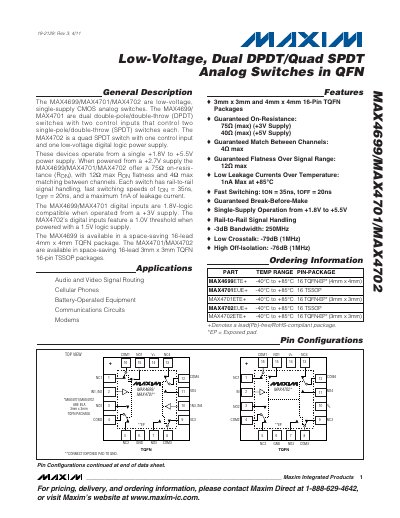
The MAX4699, MAX4701, and MAX4702 are low‑voltage CMOS analog switches that operate from a single +1.8 V to +5.5 V supply. MAX4699 and MAX4701 provide dual double‑pole/double‑throw (DPDT) switching, while MAX4702 offers a quad single‑pole/double‑throw (SPDT) configuration. Typical applications include audio/video signal routing, cellular phones, battery‑operated equipment, communications circuits, and modems.
Key electrical characteristics include a guaranteed on‑resistance of 75 Ω at a +2.7 V supply, fast switching times of 35 ns (turn‑on) and 20 ns (turn‑off), leakage currents no greater than 1 nA, a -3 dB bandwidth of 250 MHz, crosstalk of –79 dB at 1 MHz, and off‑isolation of –76 dB at 1 MHz. The devices are offered in space‑saving 16‑lead TQFN (4 mm × 4 mm) and TSSOP (3 mm × 3 mm) packages.
| Supply Voltage Range | +1.8 V to +5.5 V |
|---|---|
| On‑Resistance (RON) | 75 Ω (max) at +2.7 V |
| Turn‑On Time | 35 ns |
| Turn‑Off Time | 20 ns |
| Leakage Current | ≤ 1 nA |
| -3 dB Bandwidth | 250 MHz |
| Crosstalk (1 MHz) | –79 dB |
| Off‑Isolation (1 MHz) | –76 dB |
They operate from a single +1.8 V to +5.5 V power supply.
The on‑resistance is guaranteed to be 75 Ω (max).
Turn‑on time is 35 ns and turn‑off time is 20 ns.
The maximum leakage current is 1 nA.