
The MAX4814E DVI/HDMI 2:4 Low-Frequency Fanout Switch is a bidirectional 2:4 HDMI switch that provides routing for low-frequency signals. It consists of five single-pole/single-throw (SPST) channels, two of which have a low 3Ω (typ) on-resistance to route +5V and drain (ground return), and three to route data. The device features a mode input to control the device through an I2C interface or direct-control logic inputs. The MAX4814E is available in a 64-pin (10mm x 10mm) TQFP package and operates over the -40°C to +85°C extended temperature range.
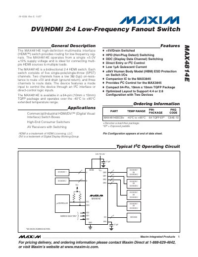
The MAX4814E high‑definition multimedia interface (HDMI™) switch provides routing for low‑frequency DVI/HDMI signals. It operates from a single +5.0 V ±10 % supply and supports both I²C and direct‑control logic modes via the MODE pin.
Key features include five SPST channels (two low‑resistance 3 Ω for +5 V/ground and three 12 Ω for data), ±6 kV HBM ESD protection, a 64‑pin TQFP package (10 mm × 10 mm), and operating temperature range from –40 °C to +85 °C. Detailed electrical characteristics, pin descriptions, and register maps are provided for system integration.
| Supply Voltage (VDD) | 4.5 V – 5.5 V |
|---|---|
| Operating Temperature Range | -40 °C to +85 °C |
| On‑Resistance (low‑resistance channels) | 3 Ω (typ) |
| ESD Protection (HBM) | ±6 kV |
It operates from a single +5.0 V ±10 % supply voltage.
The device can be controlled either through an I²C interface or by direct‑control logic inputs using the MODE pin.
Those channels have a typical on‑resistance of 3 Ω.
It provides ±6 kV HBM ESD protection on its I/O pins.