
the sg3524n/sg3524d/sg3524dr incorporate all the functions required in the construction of a regulating power supply, inverter, or switching regulator on a single chip.
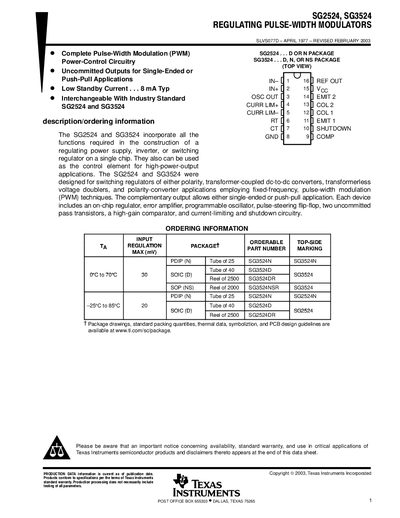
The SG2524 and SG3524 are fixed‑frequency pulse‑width‑modulation voltage‑regulator control circuits. The datasheet provides detailed electrical characteristics, absolute maximum ratings, recommended operating conditions, and typical performance curves for both devices.
The document also includes functional block diagrams, oscillator and timing design guidance, mechanical package data, and a legal notice. It is intended for designers who need to integrate these regulators into switching power supplies, inverters, or other PWM‑controlled applications.
| Supply voltage range | 8 V – 40 V |
|---|---|
| Maximum collector‑emitter breakdown voltage | 40 V |
| Package thermal impedance (D package) | 73 °C/W |
The devices operate with a supply voltage from 8 V to 40 V.
The maximum collector‑emitter breakdown voltage is 40 V.