
MAX351/MAX352/MAX353 are precision, quad, single-pole single-throw (SPST) analog switches. The MAX351 has four normally closed (NC) switches, and the MAX352 has four normally open (NO) switches. The MAX353 has two NO and two NC switches. All three parts offer low on resistance (less than 35Ω), guaranteed to match within 2Ω between channels and to remain flat over the analog signal range (∆3Ω max). They also offer low leakage (less than 250pA at +25°C and less than 6nA at +85°C) and fast switching (turn-on time less than 175ns and turn-off time less than 145ns). The MAX351/MAX352/MAX353 are fabricated with Maxim’s new improved 44V silicon-gate process. Design improve- ments guarantee extremely low charge injection (10pC), low power consumption (35µW), and electrostatic discharge (ESD) greater than 2000V. The 44V maximum breakdown voltage allows rail-to-rail analog signal handling. These monolithic switches operate with a single positive supply (+10V to +30V) or with split supplies (±4.5V to ±20V) while retaining CMOS-logic input compatibility and fast switching. CMOS inputs provide reduced input loading.
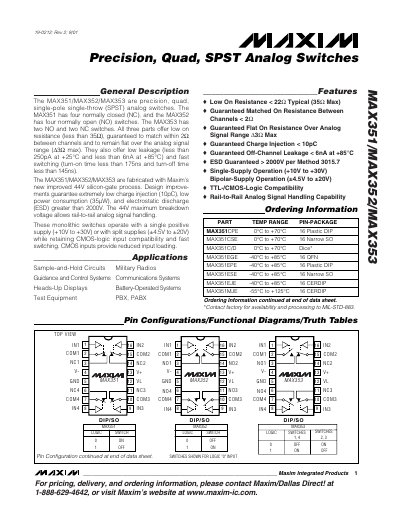
The MAX351, MAX352 and MAX353 are precision, quad, single‑pole single‑throw (SPST) analog switches fabricated with Maxim’s 44 V silicon‑gate process. The MAX351 provides four normally‑closed (NC) switches, the MAX352 four normally‑open (NO) switches, and the MAX353 offers two NO and two NC switches. All devices feature low on‑resistance, low leakage, fast switching, and high ESD protection, and they operate from a single‑supply (+10 V to +30 V) or bipolar supplies (±4.5 V to ±20 V).
The datasheet details absolute maximum ratings, electrical characteristics (on‑resistance, leakage currents, charge injection, supply currents), pin configurations for DIP, SO and QFN packages, and application information such as sample‑and‑hold circuits, military radios and test equipment. Test circuit diagrams and package drawings are also provided for design reference.
| On‑Resistance (RON) Typical | < 22 Ω |
|---|---|
| On‑Resistance (RON) Maximum | 35 Ω |
| On‑Resistance Match Between Channels | < 2 Ω |
| Leakage Current (Off‑Channel) at +85 °C | < 6 nA |
| Leakage Current (Off‑Channel) at +25 °C | < 250 pA |
| Charge Injection | < 10 pC |
| ESD Rating | > 2000 V (Method 3015.7) |
| Supply Voltage Range (Single‑Supply) | +10 V to +30 V |
| Supply Voltage Range (Bipolar) | ±4.5 V to ±20 V |
| Maximum Breakdown Voltage | 44 V |
The typical on‑resistance is less than 22 Ω (maximum 35 Ω).
They are rated for greater than 2000 V ESD per IEC Method 3015.7.
They can run from a single supply of +10 V to +30 V or from bipolar supplies of ±4.5 V to ±20 V.
Off‑channel leakage is guaranteed to be less than 6 nA at +85 °C.