
The MAX1677 is a compact, high-efficiency, dual-output boost converter designed for portable devices that require two regulated power supplies, typically for logic and liquid crystal displays (LCDs). It can operate with inputs as low as 0.7V, making it compatible with 1, 2, or 3-cell alkaline, NiCd, or NiMH batteries as well as 1-cell lithium-ion batteries. The device does not require external FETs and can maintain regulation while consuming only 20µA, making it ideal for hand-held pen-input and PDA devices operating with low-current sleep states. The primary regulator of the MAX1677 can supply up to 350mA at a factory-preset 3.3V or an adjustable 2.5V to 5.5V output. On-chip synchronous rectification provides efficiencies up to 95%. The 300kHz (or externally clocked) pulse-width-modulation (PWM) operation is particularly suitable for applications requiring low noise, such as those with wireless features. The primary converter also features pin-selectable pulse-frequency-modulation (PFM) operation that consumes only 20µA. A 1µA shutdown state further minimizes battery drain. The MAX1677's secondary step-up converter supplies up to +28V or -28V for LCD bias, varactor tuning, or other high-voltage, low-current functions. Other features of the MAX1677 include a precision reference, logic control inputs for both regulators, and an uncommitted comparator for low-battery detection or a reset function. The MAX1677 is supplied in Maxim's compact 16-pin QSOP package, which occupies minimal space.
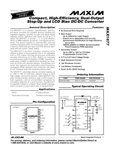
The MAX1677 is a high‑efficiency, dual‑output DC‑DC converter designed for portable devices that need both logic and LCD supply voltages. It operates from input voltages as low as 0.7 V and can accept 1‑3 cell alkaline, NiCd, NiMH or a single Li‑ion battery.
The device features a primary boost regulator with up to 350 mA output (adjustable 2.5 V‑5.5 V or fixed 3.3 V) and a secondary converter that provides selectable positive or negative LCD bias up to ±28 V. On‑chip synchronous rectification and selectable PWM or low‑power PFM modes give efficiencies up to 95 % while consuming only 20 µA quiescent current.
| Main Output Current | Up to 350 mA |
|---|---|
| Secondary Output Voltage | ±28 V (adjustable) |
| Efficiency | Up to 95 % |
| Quiescent Current | 20 µA (active), 1 µA (shutdown) |
| Package | 16‑pin QSOP |
| Operating Temperature Range | -40 °C to +85 °C |
The primary regulator can deliver up to 350 mA.
The device draws only about 20 µA when active.
The secondary converter can provide up to ±28 V for LCD bias.