
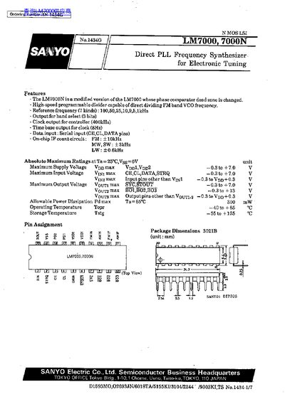
The LM7000 and LM7000N are direct‑PLL frequency synthesizer ICs for electronic tuning. They feature a high‑speed programmable divider, multiple reference frequency options, band‑select outputs, and a controller clock output. The LM7000N differs from the LM7000 only by a modified phase‑detector dead zone.
The document provides absolute maximum ratings, allowable operating conditions, pin assignments, electrical characteristics, and layout recommendations for low‑noise operation. Sample connection diagrams and usage notes for the PLL‑IC are also included.
| Supply Voltage Vpp1 (PLL operation) | 4.5 V to 6.5 V |
|---|---|
| Supply Voltage Vpp2 (Xtal OSC time base) | 3.5 V to 6.5 V |
| Input ‘H’-Level Voltage (CE, CL, DATA, STRQ) | 2.2 V to 6.5 V |
| Input ‘L’-Level Voltage (CE, CL, DATA, STRQ) | 0 V to 0.7 V |
| Output Voltage Vout (SYC, STOUT) | 0 V to 6.5 V |
| Output Voltage Vout (BO1, BO2, BO3) | 0 V to 13 V |
| Output Current (BO1, BO2, BO3) | 0 mA to 3.0 mA |
| Reference Frequency Options | 100, 50, 25, 10, 9, 5, 1 kHz |
| Operating Temperature Range | -40 °C to +85 °C |
| Maximum Power Dissipation | 300 mW |
The LM7000N has a modified phase‑detector dead zone (5‑10 ns) while the LM7000’s dead zone is 0 ns; otherwise they are identical.
Place the PLL‑IC near a ground pattern and keep it away from noisy circuitry; surround it with a ground plane to minimise interference.
Vpp1 should be 4.5 V to 6.5 V and Vpp2 should be 3.5 V to 6.5 V.